

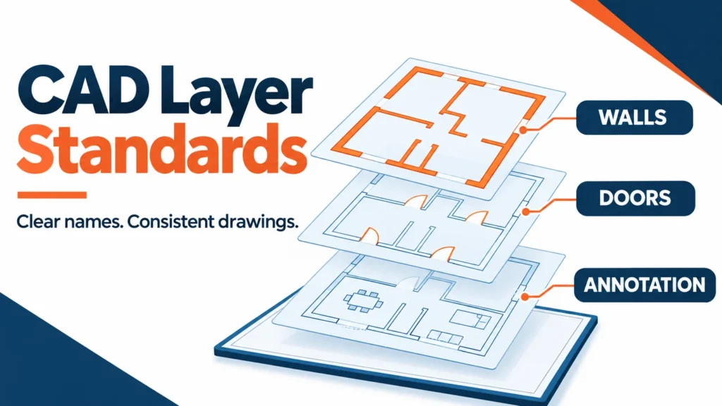
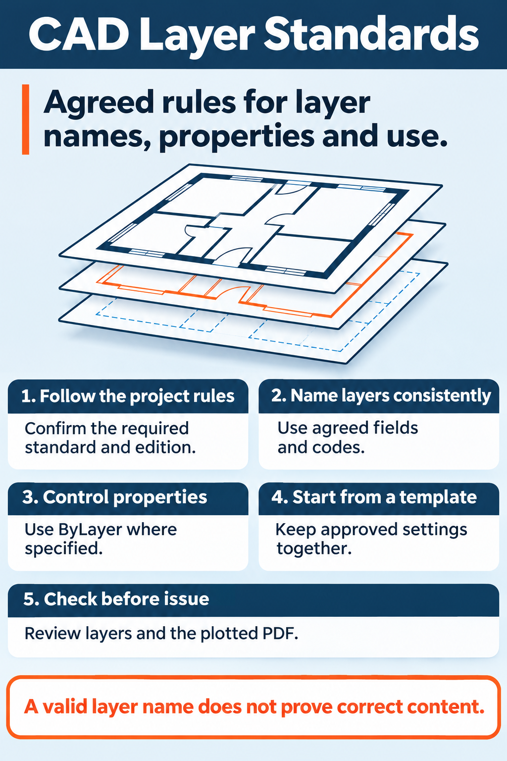
CAD layer standards are agreed rules for naming, organising and using drawing layers. A practical project standard also defines layer properties, visibility and plotting requirements. It helps different drafters produce files that colleagues can understand, edit and issue consistently. Start with the client’s requirements and nominated standard, then apply the approved template and check both the drawing and its plotted output.
For Australian construction teams, layers affect more than screen appearance. They influence how drawings are coordinated, how existing and proposed work are separated, and how information reaches consultants and asset owners. A familiar layer name is useful only when the correct objects and settings sit behind it.
If maintaining drawing standards is stretching your team, Cost Solution helps Australian businesses add dedicated Filipino drafting staff who work within their templates, software and review processes.
What should CAD layer standards cover?
A layer groups objects for a defined purpose, such as walls, dimensions or mechanical ductwork. The standard tells users what belongs in that group and how it should behave. This makes selective display and editing more predictable when several people contribute to a drawing.
A naming convention is one part of the arrangement. A useful implementation also records the properties, exceptions and checking responsibilities needed to produce consistent deliverables.
| Item | What to define |
|---|---|
| Names and descriptions | Approved fields, codes, separators and intended content |
| Object properties | Colour, linetype, lineweight and permitted overrides |
| Visibility and plotting | Non-plot layers, viewport settings and required plot styles |
| Templates and references | Approved starting files, blocks and external reference handling |
| Change control | Who approves new layers and maintains the standard |
Which CAD layer standard applies in Australia?
Confirm the project requirements before adopting a downloaded layer list. International standards, Australian publications, client manuals and office conventions can serve different purposes. Resolve conflicting requirements with the nominated project authority rather than quietly combining incompatible naming systems.
ISO 13567-1:2017 establishes general principles for structuring CAD layers, while Part 2 addresses their organisation and allocation on construction projects. These references provide a framework; they do not make every commonly used layer abbreviation suitable for every project.ISO 13567-2:2017: Concepts, format and codes used in construction documentation
Edition numbers matter. Standards Australia lists AS 13567.1-1999 as an adoption of ISO 13567-1:1998. Do not assume that an Australian publication with a similar number automatically reproduces the later 2017 ISO edition. Confirm the document and edition nominated for the work.AS 13567.1-1999: Overview and principles
The US National CAD Standard’s AIA CAD Layer Guidelines are another recognised reference, but their presence in a template does not establish Australian project acceptance. For a local client-specific example, Transport for NSW’s published Digital Engineering Standard Part 2, version 4.1, sets out its own CAD layer naming structure. Check the applicable contract and controlled requirements for your project.Digital Engineering Standard Part 2: Requirements
How to build a readable layer naming convention
A structured name separates information into agreed fields. Depending on the adopted system, those fields might identify discipline, element, presentation or work status. Use a controlled code list so different people do not invent competing abbreviations for the same content.
Illustrative office example: in A-WALL-N, the team could define A as architectural, WALL as wall geometry and N as new work. The following examples demonstrate a simple convention; they are not a claim of compliance with ISO, an Australian Standard or a particular client manual.
| Example name | Defined purpose |
|---|---|
A-WALL-N |
New architectural wall geometry |
A-WALL-E |
Existing walls to remain |
A-WALL-D |
Walls identified for demolition |
A-ANNO-DIMS |
Architectural dimension annotations |
M-DUCT-N |
New mechanical ductwork geometry |
Specify which fields are mandatory, when optional fields are allowed and what each code means. Avoid names such as misc, newlayer2 or a drafter’s initials: they explain little about the drawing content. Give users a route to request additional layers when the approved register does not cover a legitimate need.
Control colour, linetype and lineweight with ByLayer
Where the project requires it, set object colour, linetype and lineweight to ByLayer. The object then inherits those properties from its layer. Changing an approved layer setting can update the related objects without editing them individually.
Direct object overrides can defeat that control. A wall may remain visually heavy after its layer changes because the object carries its own lineweight. Define permitted exceptions, including block behaviour and viewport overrides, instead of treating every override as either acceptable or automatically wrong.
Keep plotting rules with the layer register. In AutoCAD, colour-dependent plot styles use CTB tables, while named plot styles use STB tables. Named styles can be assigned independently of colour. There is no universal rule that a particular screen colour must always produce one lineweight.About Plot Styles
Handle Layer 0, blocks and non-plot information deliberately
Use meaningful layers for ordinary project geometry. Layer 0 has a special role in block behaviour: block components created on Layer 0 with ByLayer properties can inherit properties from the insertion layer. A blanket instruction to remove Layer 0 from every block can therefore change intended behaviour.Block Object Properties Reference
Define a dedicated non-plot layer for construction guides or viewport boundaries where appropriate. Do not rely on an informal habit of putting unrelated content on Defpoints. Record the intended Plot/No Plot setting and inspect the output before issue.

Put the standard into a working template
A written guide is easier to follow when the starting file already contains the approved setup. Build a project DWT template with agreed layers, descriptions, styles, layouts and page setups. Distribute the required plot-style files and reference resources alongside it.
Test a representative sheet before rolling the template out. Include typical geometry, dimensions, blocks, hatches and reference files. Check that the drawing can be edited and plotted on another team member’s workstation using the shared resources.
Assign an owner and revision to the template package. When a rule changes, explain what changed and whether existing drawings need updating. Otherwise, a current manual can coexist with an older template that keeps reintroducing the same inconsistency.
Introduce the standard without confusing live projects
Start with a small representative drawing package rather than immediately renaming layers across every active job. Identify the project requirements, compare the existing layer register and document the proposed changes. Keep a copy of the original files so reviewers can trace what was altered.
Ask a drafter who did not build the template to complete a short task with it. Can they find the correct layer, distinguish existing work from new work and produce the expected PDF? Questions raised during this exercise often reveal unclear descriptions or missing instructions before those gaps spread across a larger drawing set.
Agree a transition point for ongoing projects. Some may retain their approved setup, while new work starts with the revised package. Record that decision so a well-intended cleanup does not introduce a second naming system halfway through an issue.
Review incoming drawings and BIM exports
Consultant drawings can introduce unfamiliar layers, duplicate naming patterns and object overrides. Preserve the incoming file, review its purpose, and agree any mapping before translating content. Avoid merging layers merely because their names look similar: existing and demolition geometry may need to remain separate.
For Revit exports, map categories and subcategories to the required CAD layers in the DWG/DXF export setup. Review how view-specific overrides are exported, because the chosen option can preserve object overrides or create additional layers. Inspect a sample DWG rather than assuming a good-looking Revit view guarantees compliant CAD output.Layer Mapping for DWG/DXF Export
How to check CAD layer standards before issue
Where supported by your AutoCAD edition and platform, save the approved layer and style definitions in a DWS standards file, associate it with the drawing using STANDARDS, and run CHECKSTANDARDS. Review proposed fixes before applying them.
“The audit checks both the named object, such as the layer or style name, and properties of that object.”
Frank Mayfield, writing for Autodesk, in CAD Standards Checker: Exploring the Features and Benefits of AutoCAD
That check has limits. Autodesk documents that the layer plug-in does not check On/Off, Freeze/Thaw, Lock or Plot/No Plot settings. It also cannot determine whether a correctly named wall layer contains the right geometry. Combine the automated check with content review and PDF inspection.About CAD Standards
- Compare layer names and properties with the approved register.
- Check objects, blocks and permitted property overrides.
- Review reference files and viewport visibility.
- Confirm non-plot settings and the selected plot-style table.
- Inspect the PDF at the intended sheet size and scale.
- Record exceptions and obtain the required approval.
Example: keeping refurbishment drawings clear
Hypothetical example: a refurbishment team receives a plan with existing partitions and proposed walls on one generic layer. Applying a new colour does not solve the underlying problem: users still cannot isolate demolition work reliably.
The team confirms the design status, separates the relevant geometry into approved layers and checks the resulting sheets. The improvement comes from classifying the objects correctly and applying the agreed presentation rules together.
For review, the drafter can isolate the demolition layers and compare the visible objects with the authorised markup. They can then restore the intended sheet view and inspect the plotted PDF. If a wall was placed on an approved layer with the wrong status, a naming check may still pass. That is why checking the content remains a separate responsibility.
Keep your drafting team working to the same rules
Cost Solution’s construction drafting services help Australian businesses build dedicated offshore teams in the Philippines. Your drafter can use your layer register, templates and checking procedures, while your project team retains technical direction and review.
Provide a current template, an approved example drawing and a clear contact for questions. Consistent feedback helps a dedicated drafter apply your requirements across future projects.
Need dedicated drafting capacity that works within your standards? Contact Cost Solution on +61 451 442 120.
Frequently asked questions
Is there one universal CAD layer list?
No. Recognised frameworks exist, but required names, codes and properties depend on the adopted standard and project requirements. Confirm those before creating the template.
Are layer colours the same as printed lineweights?
Not automatically. The plot-style setup and object properties affect the output. Use the project’s approved settings and check the plotted sheet.
Does passing a DWS check mean a drawing is ready?
No. It checks supported names and properties against the associated standards file. Geometry, information accuracy, visibility and issue readiness still need review.


Have a question or a different perspective?
Share your experience with the construction community.
Be the first to start the conversation.